
|
|
|||
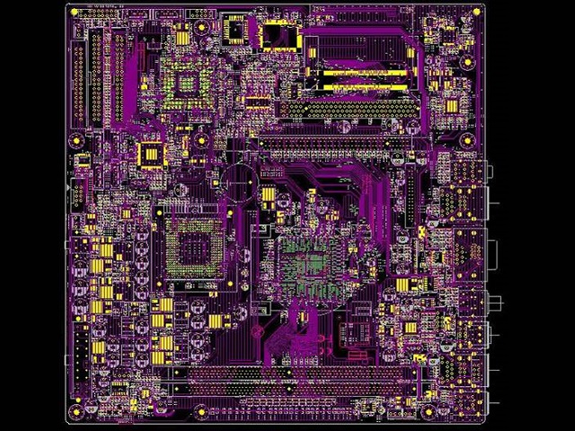
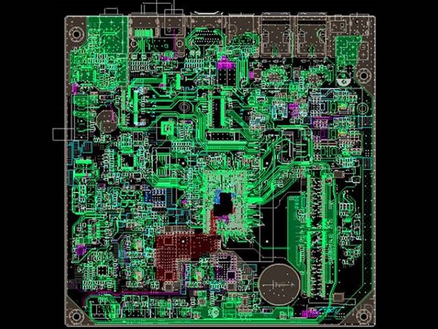
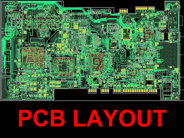
To efficiently promote the design of a PCB (Printed Circuit Board) from schematic entry to final gerber output, the following steps can be followed using PCB design software (like Orcad Allegro KiCad, Altium Designer, or Eagle):
1.Schematic Entry• Component Placement:Using the schematic editor, add and interconnect components by referring to the circuit diagram.
• Electrical Rules Check (ERC):Perform an ERC to check for any schematic errors like unconnected pins or inconsistent connections.
• Assign Footprints:For each schematic symbol, assign the correct PCB footprint, ensuring you match the physical package. 2.Component Placement
• Netlist Import:Generate a netlist from the schematic and import it into the PCB layout tool.
• Board Outline:Define the physical dimensions and shape of the PCB.
• Place Components:Place the components on the board in a logical and space-efficient manner, respecting design constraints such as clearances.
• Use Design Rules:Define design rules (trace width, spacing, via sizes, etc.) based on manufacturing capabilities. 3.Track Routing
• Routing Mode:Select between manual or auto-routing modes. Manual routing gives you more control over signal paths.
• Signal Layer Usage:For multilayer PCBs, decide which layers will carry which signals (top, bottom, or inner layers for power and ground planes).
• Via Usage:Use vias to change layers when necessary for routing complex connections.
• Power and Ground Planes:Pour ground and power planes for noise reduction and stability.
• Track Width:Ensure critical traces (e.g., power, ground, high-current signals) use wider traces.
• Differential Pairs:If applicable, route differential pairs with controlled impedance. 4.Design Rule Check (DRC)
After routing, run a DRC to ensure the layout adheres to the specified rules, ensuring there are no shorts, overlaps, or clearance violations. 5.Gerber Generation
• Layer Selection:Select the appropriate layers to export, such as:
o Top Copper
o Bottom Copper
o Solder Mask (top and bottom)
o Silkscreen (top and bottom)
o Drill file for vias and holes
• Export Settings:Set up the export to include all manufacturing details such as board outline and drill locations.
• Gerber Viewer:Use a gerber viewer to inspect the exported files for correctness. 6.Bill of Materials (BOM)
Generate a BOM to provide a list of components used in the design along with their part numbers and footprints. 7.Final Review
Before sending to a manufacturer, review the entire design to ensure everything matches the design intent, including clearance checks, signal integrity, and manufacturing tolerances. Key Considerations:
• Thermal Management:Consider thermal vias and heat sinks for high-power components.
• Grounding:Ensure proper grounding for noise-sensitive circuits.
• Manufacturer Capabilities:Tailor your design rules to the PCB manufacturer's capabilities (trace width, spacing, and layer count).
• Test Points:Add test points for debugging and testing during production. By following these steps, you can ensure a smooth transition from schematic to PCB fabrication and minimize errors when sending the design for manufacturing.
| AddTime | Category | Model | Specification | Version | Data size | Download |
| MSG: NO RECORD. | ||||||